Tuesday, June 16, 2015
Flycutter build plan
Although using the previous design you could go directly to the workshop to cut metal, it is safer and more efficient to plan a little bit the operations that will be performed in order to produce the piece. This will help determine possible problems, choose the best order in which all operations should be performed and the tools to use.
Machine availability becomes a factor when planing the sequence of operations to be performed. For instance, you may have a band saw, a file, a hacksaw or a rotational tool to cut a piece of steel. Being the most common, I'll choose between a hacksaw and a rotational-tool.
0. Material selection. Mild steel (1018) should be good enough for the purpose. Its lead content is minimal and its machinability is acceptable. Its rigidity is better than that of Aluminum, which will help when performing the cuts.
0.1. Use eye protection and a mask to protect the lungs from the cutting tool debris.
1. Cut a piece of metal of length 81mm and diameter 1".
For this operation, a rotational tool can be used. A dremel with an abrasive disk can do the job. The disk must have at least 1/2" radius in in order to cut the piece. If those disks are not available, the operation can be initiated with the rotational tool and then completed with the hacksaw. To accomodate for errors, 82mm can be cut.
2. Indicate the piece in the lathe and make it run true.
3. Support the piece in the steady
4. Face the piece to remove saw marks.
5. Drill a 5mm counter-sink on the face
6. Mount the tailstock live center and fix it to the piece.
7. Turn the piece on the lathe using a finishing tool, reducing to 25mm over a length of 50mm. This operation can be performed with a right hand tool.
8. Invert the piece in the lathe
9. Repeat 2-6 on this side
10. Turn the piece on the lathe reducing to 10mm diameter over a length of 30mm
11. Fix the part to the milling machine using a sine vise or angle vise.
The angle needs to be 15 degrees.
12. Mill this base of the part.
13. Mill the screw cuts and the tool cut.
14. Mount the piece horizontally on the vise and drill the screw holes.
15. Tap the holes using the M4 tap.
16. Mill the compensation hole.
17. Chamfer all borders.
18. Grind a cutting tool.
19. Install the cutting tool into the fly-cutter head using two grub screws.
20. Clean the area
21. Clean the area again, use a magnet if available.
This should complete the build plan.
From the design, the fly-cutter will require
Materials:
A rod of 81mm 1"diameter mild steel (1018)
Two M4x4mm grub screws.
Tools:
Dial indicator
Lathe
Fixed steady
Live center
Counter sink 5mm
Right hand finishing tool
Right hand tool
1"-2" Micrometer
25mm Micrometer
Sine vise/Angle vise
10mm mill bit
8mm mill bit
#30 drill bit
M4 tap
File
Milling machine
Rotational tool (Dremel?)
Abrasive disks for the rotational tool
Hacksaw
Designing and building a flycutter
Fly-cutters allow to perform large surface cuts with a milling machine or a lathe using cutting tools that can be ground manually, hence, they are cheap to maintain. They are also relatively easy to make, which make them a nice project for the home machinist. In this post I'll describe the process to design and build a fly-cutter using open source software and standard home-level machines.
The process begins with some hand sketches of the fly-cutter.

The stability of the cut is important. The least eccentric the fly-cutter is, the better the expected results of the cutting operations. Since the fly-cutter holds a tool that protrudes through one side, it is naturally eccentric. This fact is compensated by removing some material on the side of the fly-cutter from which the tool protrudes. This cut needs to be calculated.
Another source of eccentricity comes from the need of using screws to hold the tool. Any cut to facilitate screw insertion needs to be compensated. As long as these cuts are symmetric, they don't require any particular calculation.
Adding compensation, the sketch becomes:

Now, the part can be modeled in any CAD program. After examining various of them, I came to the conclusion that FreeCAD is the best. The most appealing feature that it has is that it is parametric. This means that you can make up a solid base in parts and then modifying a single part modifies the solid. Not all programs allow this. By creating a couple of concentric cylinders, joining them together and subtracting an inclined box, you get to an approximation of the uncompensated sketch.


Now the tool holder canal and the screw holding cuts are subtracted as well as a compensation cut that can be build by joining a box with a cylinder


Now, the depth of the compensating cut must be estimated precisely by smart trial and error. A tool bit is added by rotating and cutting a box and the union of the tool and the fly-cutter is generated.

It is then converted to a solid using Part->Convert to Solid

And then the center of mass can be calculated by typing this in the python console:
"App.ActiveDocument.getObjectsByLabel('Cut008 (Solid)')[0].Shape.CenterOfMass"
The X axis is already very accurate because of the symmetry of the screw cuts. We are interested in the center of mass in the Y axis. Starting with a depth of 20mm, the center of mass is at 0.014mm. Changing the depth of the compensator and repeating for 15mm, the center of mass is at -0.127. By using the line equation
a = 0.014122050216471298
b = -0.1279256660190943
m = (b-a)/5
y - a = m *(x + 20)
x = -a/m - 20 = -19.503
With a depth of 19.5mm, the center of mass in the y axis is -0.0002754275297938901 mm. Being small enough and given that the length of the manually ground tool will certainly vary, I consider this sufficiently accurate. If more precision is required, the line equation process above can be iterated.
The resulting fly-cutter is then obtained.


After obtaining the model, a build plan needs to be written including the sizes, materials and tools to use for turning and milling the part.
The process begins with some hand sketches of the fly-cutter.

The stability of the cut is important. The least eccentric the fly-cutter is, the better the expected results of the cutting operations. Since the fly-cutter holds a tool that protrudes through one side, it is naturally eccentric. This fact is compensated by removing some material on the side of the fly-cutter from which the tool protrudes. This cut needs to be calculated.
Another source of eccentricity comes from the need of using screws to hold the tool. Any cut to facilitate screw insertion needs to be compensated. As long as these cuts are symmetric, they don't require any particular calculation.
Adding compensation, the sketch becomes:

Now, the part can be modeled in any CAD program. After examining various of them, I came to the conclusion that FreeCAD is the best. The most appealing feature that it has is that it is parametric. This means that you can make up a solid base in parts and then modifying a single part modifies the solid. Not all programs allow this. By creating a couple of concentric cylinders, joining them together and subtracting an inclined box, you get to an approximation of the uncompensated sketch.


Now the tool holder canal and the screw holding cuts are subtracted as well as a compensation cut that can be build by joining a box with a cylinder


Now, the depth of the compensating cut must be estimated precisely by smart trial and error. A tool bit is added by rotating and cutting a box and the union of the tool and the fly-cutter is generated.

It is then converted to a solid using Part->Convert to Solid
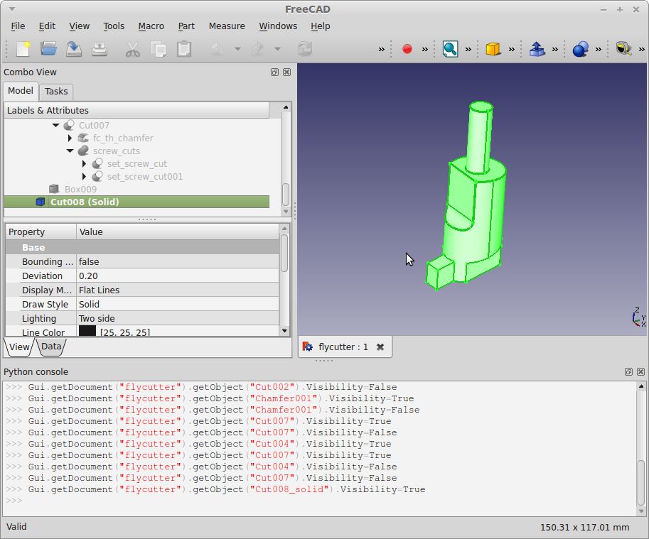
And then the center of mass can be calculated by typing this in the python console:
"App.ActiveDocument.getObjectsByLabel('Cut008 (Solid)')[0].Shape.CenterOfMass"
The X axis is already very accurate because of the symmetry of the screw cuts. We are interested in the center of mass in the Y axis. Starting with a depth of 20mm, the center of mass is at 0.014mm. Changing the depth of the compensator and repeating for 15mm, the center of mass is at -0.127. By using the line equation
a = 0.014122050216471298
b = -0.1279256660190943
m = (b-a)/5
y - a = m *(x + 20)
x = -a/m - 20 = -19.503
With a depth of 19.5mm, the center of mass in the y axis is -0.0002754275297938901 mm. Being small enough and given that the length of the manually ground tool will certainly vary, I consider this sufficiently accurate. If more precision is required, the line equation process above can be iterated.
The resulting fly-cutter is then obtained.


After obtaining the model, a build plan needs to be written including the sizes, materials and tools to use for turning and milling the part.
Sunday, October 21, 2012
The basic milling workflow
There are several different tools in Linux that can be used for each of these stages. Different tools suite different applications. With them you can produce circuit boards, metal pieces, plastic panels, jewerly, car pieces, and many more. Sometimes, using a good text editor such as vim or emacs can be enough for the preprocessing, however, sometimes you will need more powerful tools. There's a large community working in different tools that can be used in production to support each of the milling stages.
In this blog I'll be talking about programs, utilities and recommendations for milling in Linux.
Subscribe to:
Posts (Atom)