The process begins with some hand sketches of the fly-cutter.

The stability of the cut is important. The least eccentric the fly-cutter is, the better the expected results of the cutting operations. Since the fly-cutter holds a tool that protrudes through one side, it is naturally eccentric. This fact is compensated by removing some material on the side of the fly-cutter from which the tool protrudes. This cut needs to be calculated.
Another source of eccentricity comes from the need of using screws to hold the tool. Any cut to facilitate screw insertion needs to be compensated. As long as these cuts are symmetric, they don't require any particular calculation.
Adding compensation, the sketch becomes:

Now, the part can be modeled in any CAD program. After examining various of them, I came to the conclusion that FreeCAD is the best. The most appealing feature that it has is that it is parametric. This means that you can make up a solid base in parts and then modifying a single part modifies the solid. Not all programs allow this. By creating a couple of concentric cylinders, joining them together and subtracting an inclined box, you get to an approximation of the uncompensated sketch.


Now the tool holder canal and the screw holding cuts are subtracted as well as a compensation cut that can be build by joining a box with a cylinder


Now, the depth of the compensating cut must be estimated precisely by smart trial and error. A tool bit is added by rotating and cutting a box and the union of the tool and the fly-cutter is generated.

It is then converted to a solid using Part->Convert to Solid
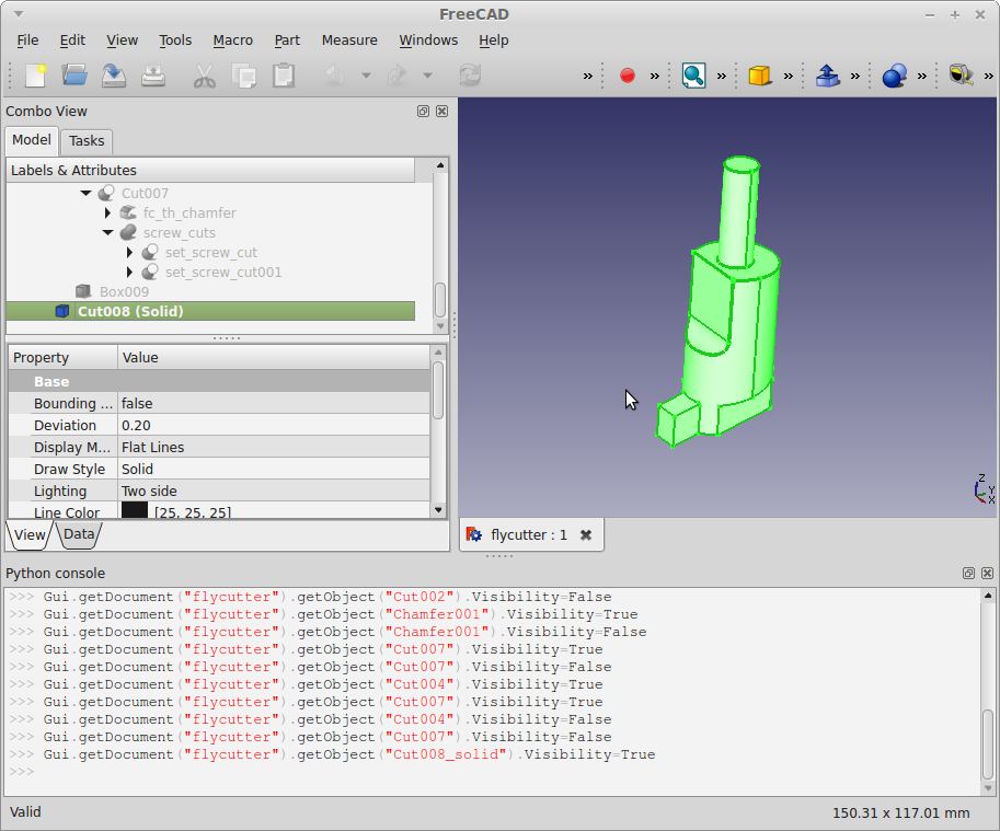
And then the center of mass can be calculated by typing this in the python console:
"App.ActiveDocument.getObjectsByLabel('Cut008 (Solid)')[0].Shape.CenterOfMass"
The X axis is already very accurate because of the symmetry of the screw cuts. We are interested in the center of mass in the Y axis. Starting with a depth of 20mm, the center of mass is at 0.014mm. Changing the depth of the compensator and repeating for 15mm, the center of mass is at -0.127. By using the line equation
a = 0.014122050216471298
b = -0.1279256660190943
m = (b-a)/5
y - a = m *(x + 20)
x = -a/m - 20 = -19.503
With a depth of 19.5mm, the center of mass in the y axis is -0.0002754275297938901 mm. Being small enough and given that the length of the manually ground tool will certainly vary, I consider this sufficiently accurate. If more precision is required, the line equation process above can be iterated.
The resulting fly-cutter is then obtained.


After obtaining the model, a build plan needs to be written including the sizes, materials and tools to use for turning and milling the part.
No comments:
Post a Comment